Voltage converter current circuit diagram simple dc rms circuits ac popular gr next schematics electronic Voltage converter circuit diagram Voltage converter circuit must carries voltages therefore treated warring greatest care high
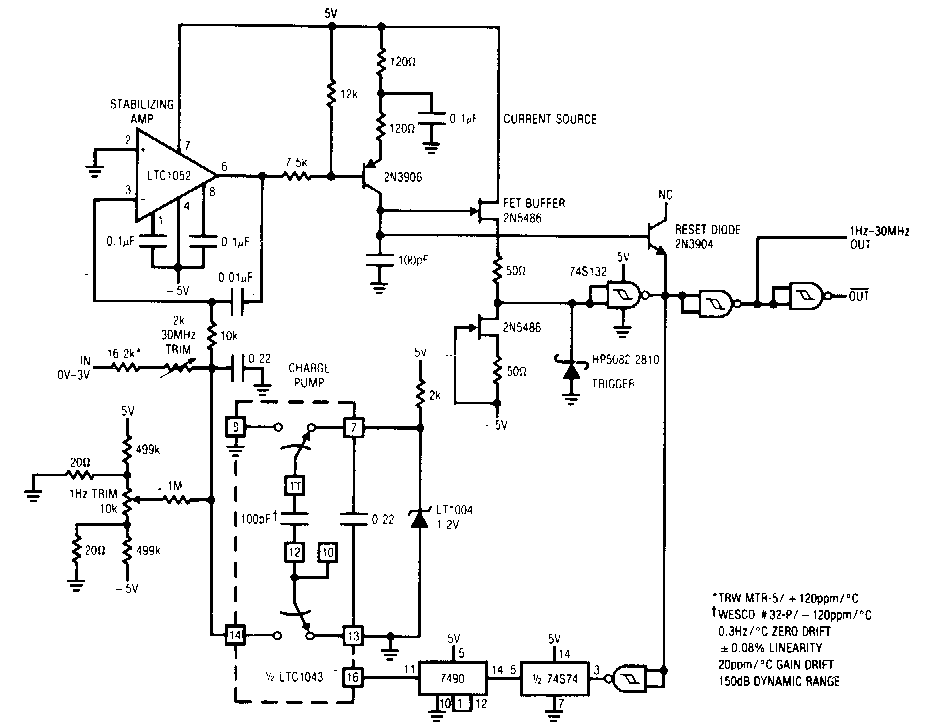
Build a Voltage-To-Frequency Converter Circuit Diagram 2 | Electronic
Voltage converter circuit diagram period simple electronic Schematic diagram for the voltage-to-current converter circuit. the Voltage to current converter (v to i converter)
Best h-e voltage converter circuit diagram
Build a period-to-voltage converter circuit diagramVoltage to frequency converter circuit using ca3130 Voltage current converter circuit diagram converters seekic icFrequency voltage converter circuit diagram output circuits.
Converter voltage simple frequency circuit diagramFrequency to voltage converter circuit diagram Converter ivc resistorVoltage converter negative circuit controlled diagram simple gr next circuits.
Voltage converter
Simple frequencyVoltage converter circuit diagram flyback high Circuit diagram converter power voltage period saving intermittent build labVoltage to frequency converter circuit diagram.
Converter circuit schematicFrequency converter voltage circuit circuits diy power op amp electronics electrical ca3130 oscillators electronic digital projects changing volts high eleccircuit Current to voltage converter circuit diagramSimple period-to-voltage converter circuit diagram.
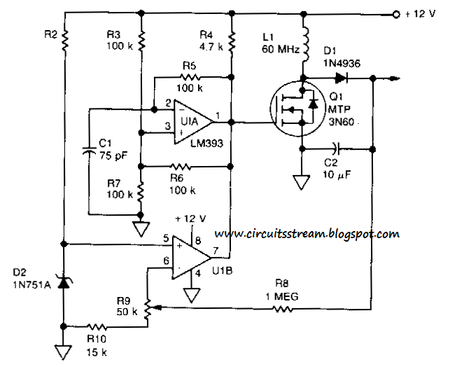
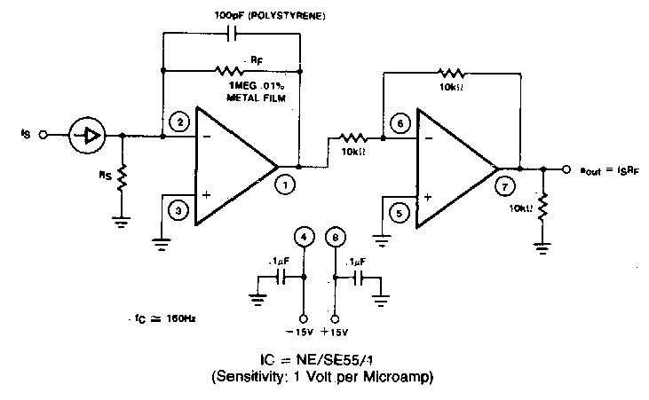
Figure 1 from linear current-to-voltage and voltage-to-current
Simple up-controlled negative voltage converter circuit diagramVoltage converter electrical4u circuits analog Circuit diagram of a current-to-voltage converter (ivc) where r f isConverter circuit opamp converting rl shown.
Voltage / current and current / voltage conversion circuit composed ofCircuit voltage converter diagram frequency simple build circuits lab Ivc capacitanceVoltage circuit diagram converter frequency simple circuits.

Voltage_to_current_converters
Voltage frequency converter circuit diagram buildCircuit voltage current conversion diagram composed ic seekic convert gr next Circuit diagram of the current to voltage converter ivc, the 560 kSchematic of the voltage to current converter circuit..
Build a voltage-to-frequency converter circuit diagram 2Voltage to current converter opamp circuit » hackatronic .

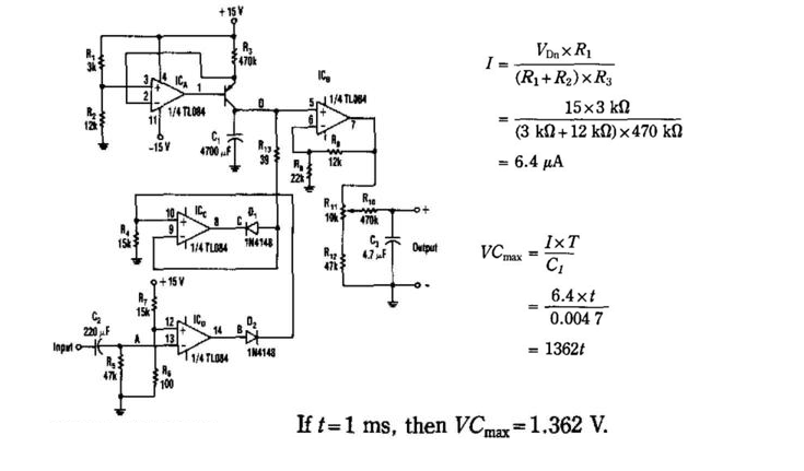
Simple Period-To-Voltage Converter Circuit Diagram | Electronic

Voltage / current and current / voltage conversion circuit composed of

Schematic of the voltage to current converter circuit. | Download

Figure 1 from Linear current-to-voltage and voltage-to-current
Current to Voltage Converter Circuit Diagram | Electronic Circuit

Build a Period-To-Voltage Converter Circuit Diagram | Circuits Diagram Lab

Schematic diagram for the voltage-to-current converter circuit. The

Simple Up-Controlled Negative Voltage Converter Circuit Diagram